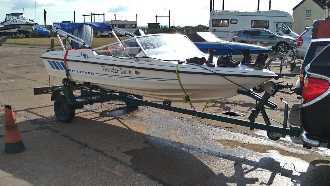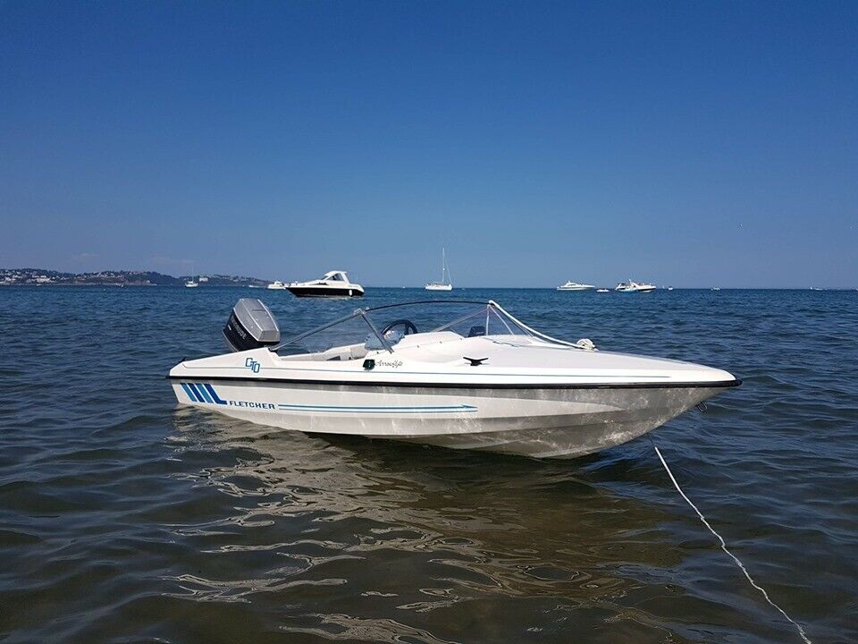
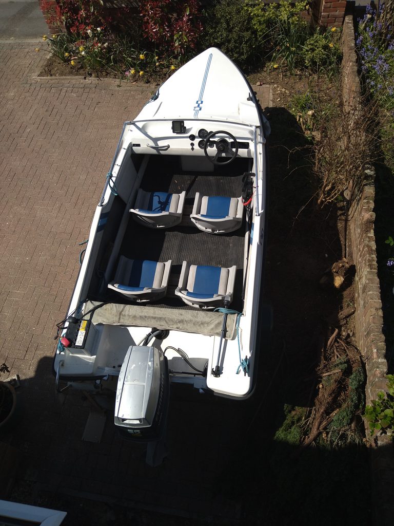
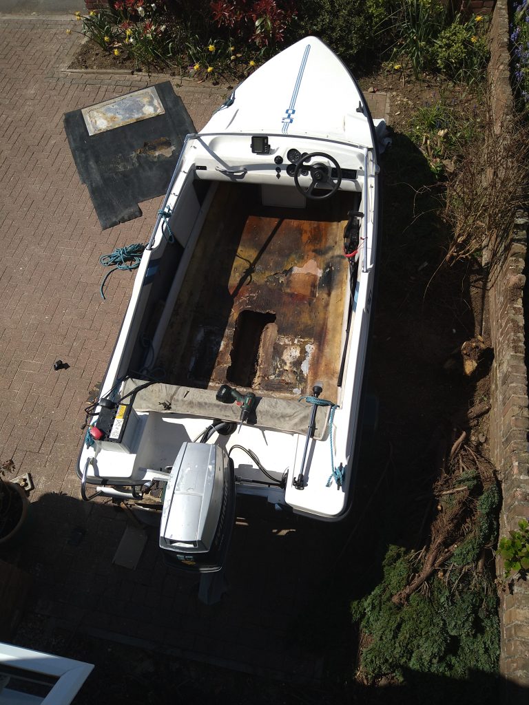
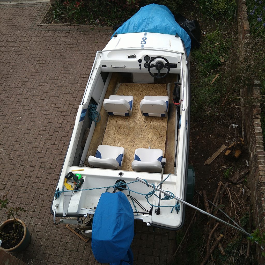
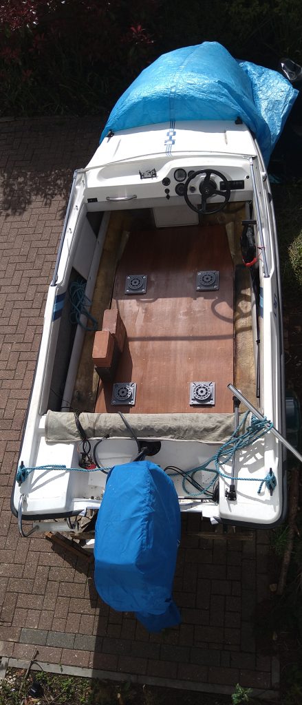
In my previous post I revealed that the floor in Thunder Duck had given way. Let’s look at what happened. So I started with the Duck as we know her. I needed to get the seats out as they were not great, and they were in the way. Here we have an aerial picture of the work about to start.
So having removed the seats it was immediately apparent that all was not well with the floor. The matting came out, to reveal an aluminium plate that was supporting the floor. This came out and the floor underneath was soft. A quick boot and….
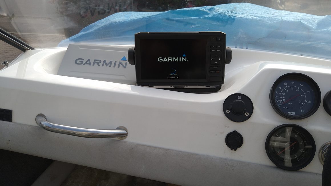
So, after a bit of head scratching and consultation of the Fletcher owners group of Facebook, the decision was taken that the floor had to come out. The new chart plotter fitment was abandoned and the focus was turned to removing the floor.
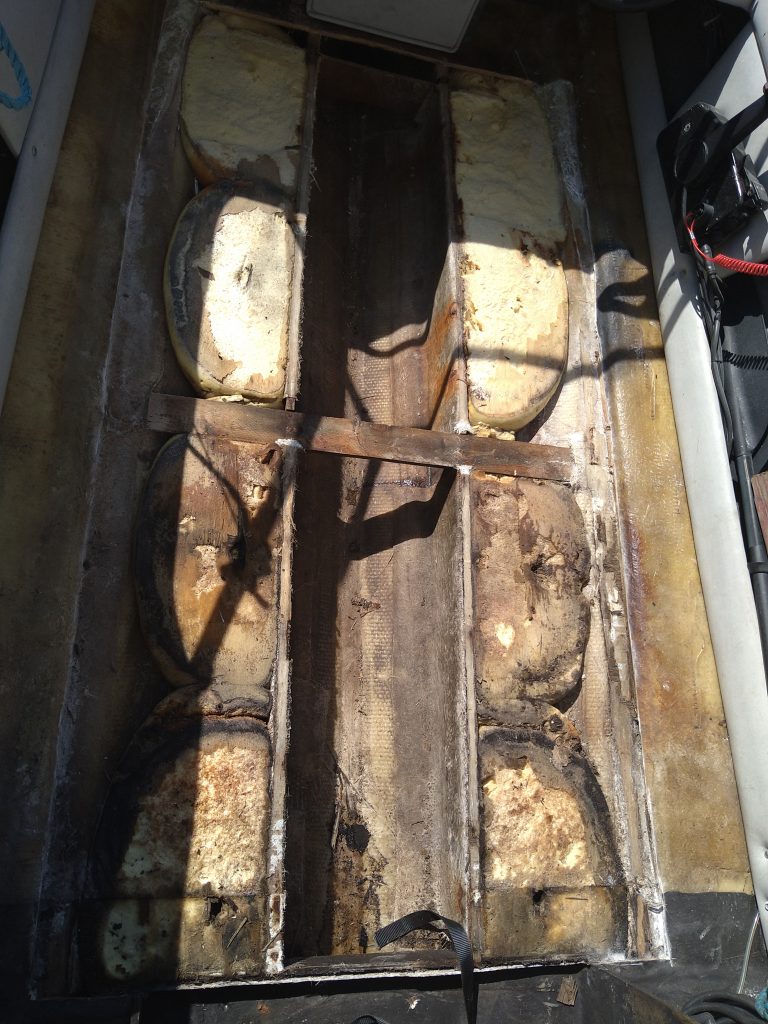
Once out then this was discovered. A Bilge and two flotation chambers, filled with sopping wet flotation foam. More consultation with, predominantly Melvyn on the group. The foam has to come out too.
Now a plan was required and Melvyn very kindly provided the details. I have followed this plan to the letter, but added my own improvisation. The structural floor is 12 mm Marine Plywood. It is expensive stuff but I found some from Travis Perkins for a good price and I had it delivered. I needed 12″ by 4″, and it was heavy stuff.
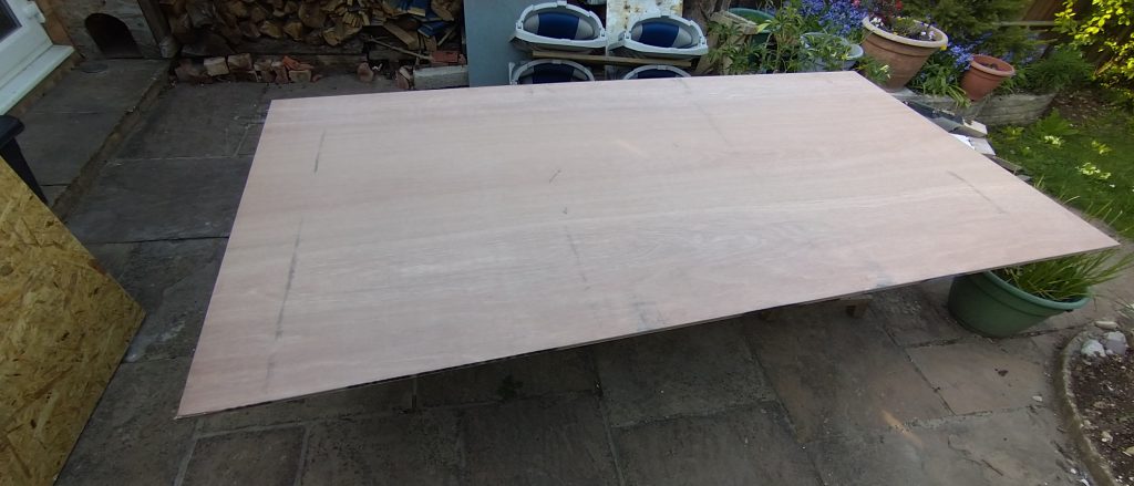
This needed cutting to fit the hull. Nothing was square and as the floor is recessed then there was no way the whole piece of ply could be put into position and marked. I would have to take lots a measurement and transfer them to the plywood. If I got this wrong then I was in trouble, probably needing a new piece of plywood.
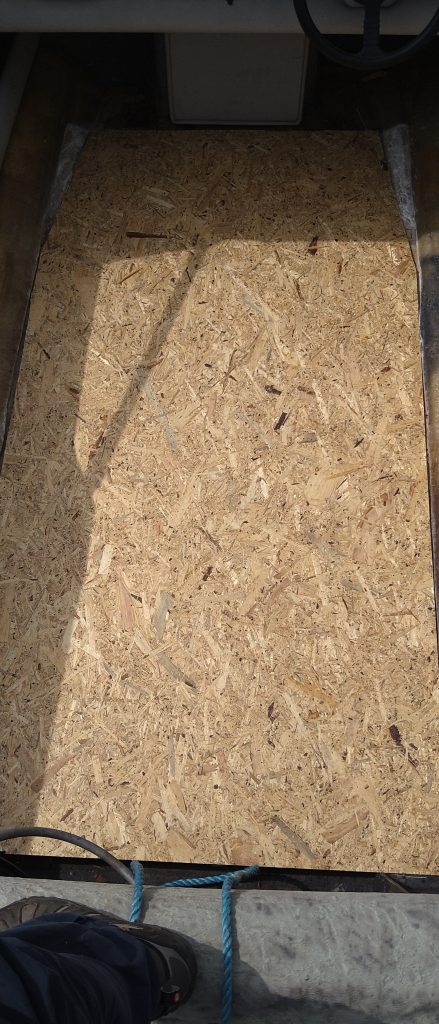
So, my improvisation was to by a piece of OSB board, which is much cheaper. I used this to create a template floor first. If I got this wrong then it wasn’t such a disaster. The first thing was to get and mark this up, cut it, trial fit it to the hull, and fettle it as necessary. This actually went very well.
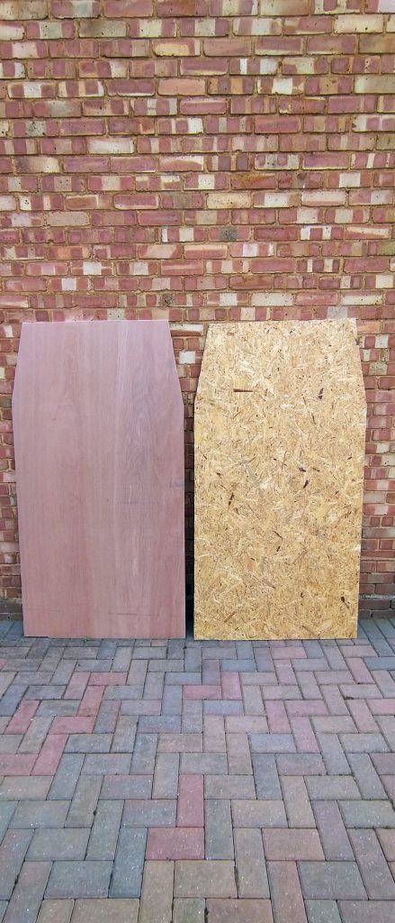
Once I was happy with the fit I then set about using the template board to cut the actual plywood.
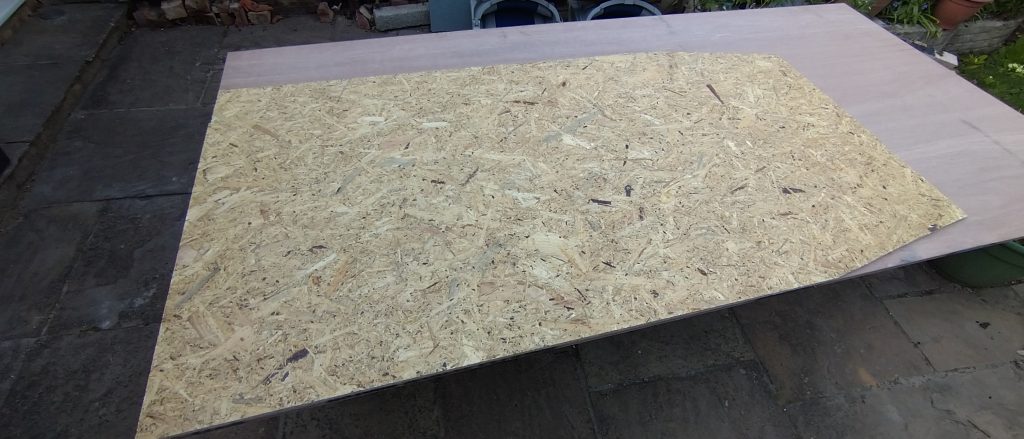
I marked it out, then cut it with the jigsaw. Then I had two floors.
Now I needed to deal with the foam. This is a legal requirement that the boat has enough buoyancy to remain afloat if fully flooded and with two people on board. The polyurethane foam is made using a pair of chemicals that are mixed together and then poured where it is needed, I obtained the required chemicals from “East coast Fibreglass Supplies”. This and the Plywood were the two items I didn’t source through EBay.
The chemicals were mixed in batches and poured. They then expanded out and set hard. I gave then a few days to really set off hard.
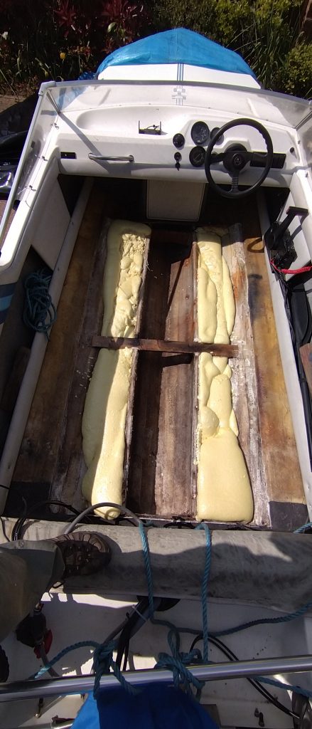
Then it was a matter of cutting the over-fill off using a hand saw.
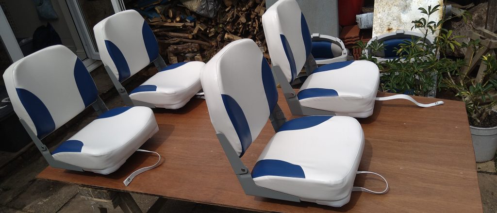
Next I needed to consider the seats. I was always intending to fit new seats and this is what I chose.
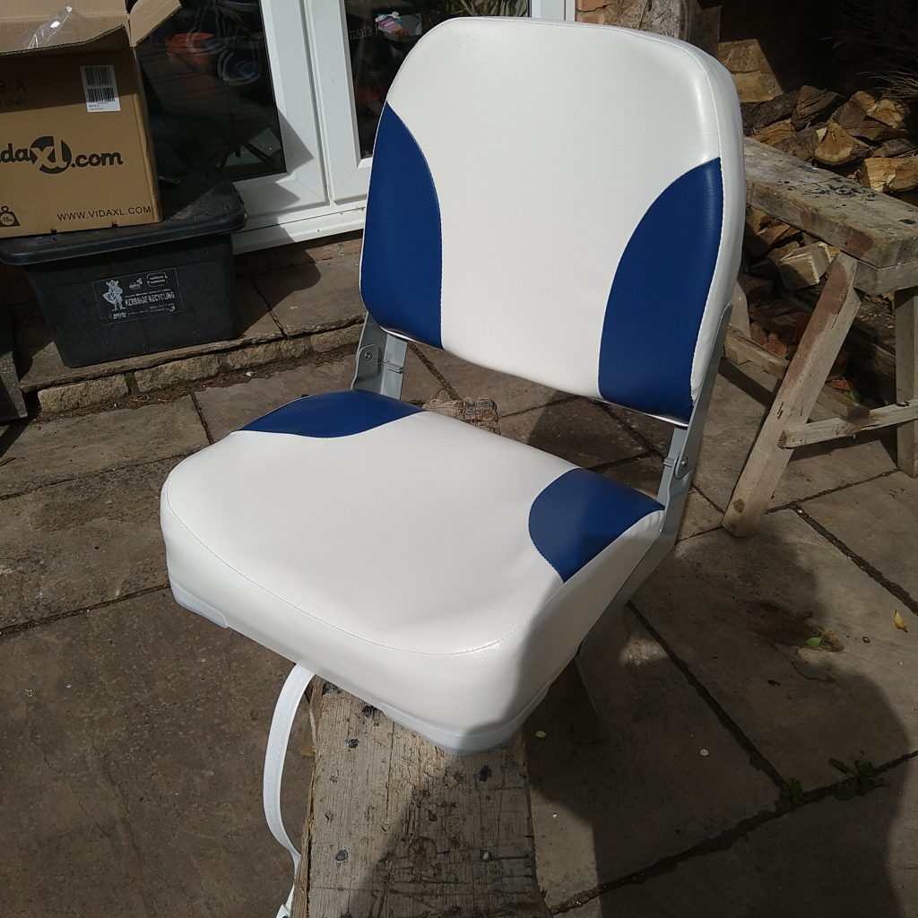
Once the seats arrived I realised they had no bases, so a quick search found bases that would raise them up, would allow the seats to rotate, and also allow the seats to be removed for storage.
Once the bases had arrived I then set about determining where the seats would be positioned. To do this I used the template floor so I could scribble all over it. I ended up screwing the seats down temporarily to really try it out.
Once this was all marked up I returned to the work bench, squared everything up and get the seats straight. Then I drilled through the template board with the 7.5 mm drill required for the M6, stainless steel bolts, that need to go through the floor.
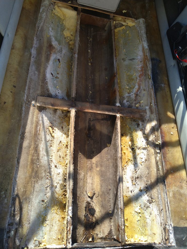
The next task was to accurately locate the wooden stringers, under the floor that support it. I needed to screw the floor down with stainless steel wood screws, into the end of Marine Ply, so I needed to be accurate. I had a rough line on the template, so I used the router to cut four viewing slots along this line on each stringer. I then put the template floor into the hull and adjusted the line to suit what I could see through the slots. Once done I was able to mark and drill the holes for the retaining screws.
I could now work on the plywood itself. The first job was to coat it in Resin, on all faces, to waterproof it. Once that was cured I could clamp the template floor to it and then drill all the holes through.
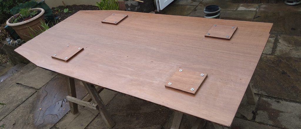
Now attention turned to the seat mounts. The floor needs re-enforcing under each seat, and to do this I cut four pieces of additional Marine ply, from the off-cuts. These were the sizes of the bases. I then flipped the floor over and placed the actual seat bases over their mounting holes. Then I drew around them, before removing them. I then Resin-ed the four pieces of ply to the underside of the floor, then Resin-ed them fully to waterproof them.
Once the resin was cured I flipped the floor back the right way and then drilled the mounting holes through the additional ply board. Once complete then the floor was flipped once more and sixteen stainless steel M6 captive nuts were hammered into position. Now the seat bases had something to bolt to.
I trial fitted the seat bases to make sure that the threads in the nuts were good and that everything was straight in the holes.
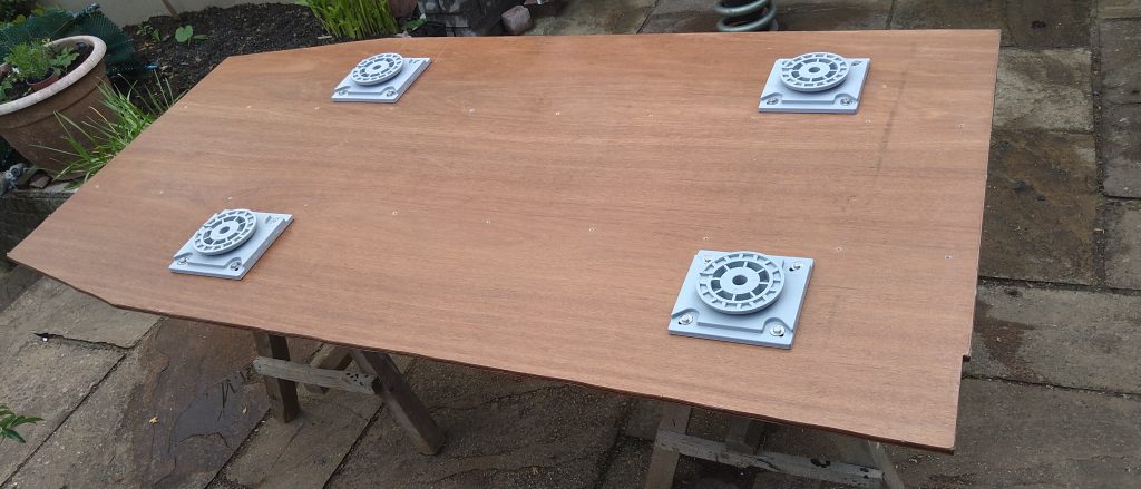
Now on a roll, I fitted the seats for the first time to the floor. All was good.
Now I was able to fit the plywood floor into the boat. But first some preparation work. The seat re-enforcement plates were going to be sited in the flotation tanks. But I had to remove some foam to let them sit in place. How to locate that? Back to the template. I chopped out the marked seat locations to leave four square holes. I then fitted the template to the boat and could then cut the foam that was below these holes. That concluded the role of the template floor.
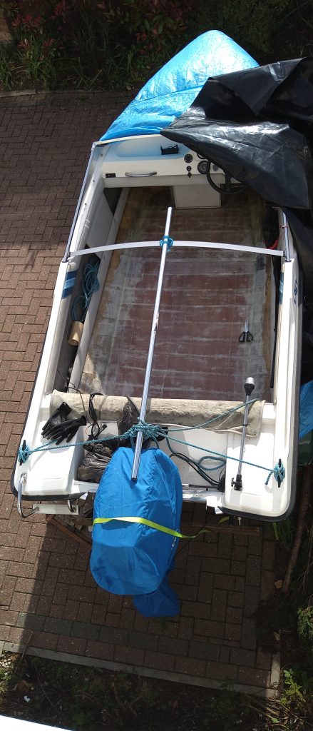
Now to make ready for the plywood final fitment. I trial fitted it and all was well. So removing it from the hull I then got busy with the Resin once more. All the foam was resin-ed to waterproof it. The stringers and the contact points on the hub were also resin-ed. Then the plywood floor was placed into position. The 20 wood screws were driven into the stringers below. There was a slight spring at the rear Port side, so I placed several bricks on that position to hold the floor down to the resin-ed hull, while it cured.
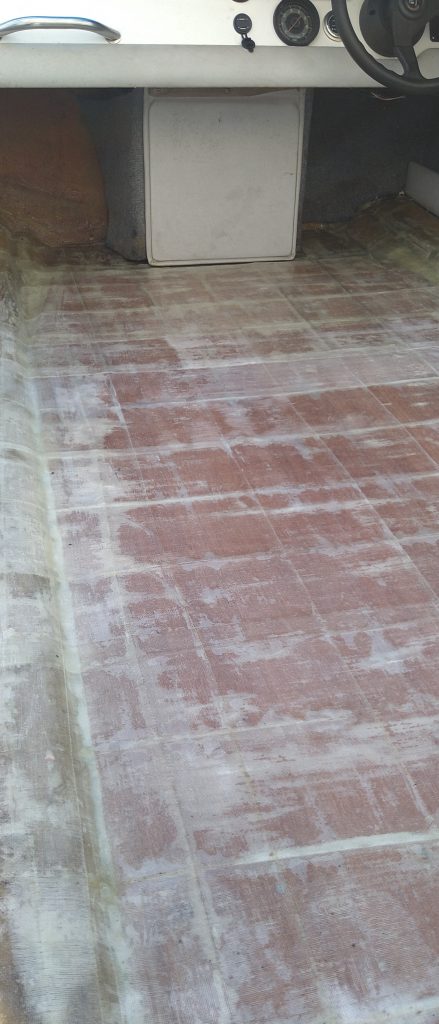
Now to the fibreglass, the resin and the creating of Glass Re-enforced Plastic (GRP). The floor is actually a structural part of the hull, so it is very important that it is well bonded to that hull. To do that the joints around the edge of the floor are first covered by three layers of fibreglass / resin. Then the floor is completely covered in exactly the same way, but over lapping the joints. R/FG/R/FG/R/FG/R.
This is the situation with about a third of the third layer of fibreglass going on. I had run out of fibreglass cloth and had to order more.
Update!. The fibreglassing you see above has been ripped out. It failed totally. I have a post about this here. I will get new pictures when I am in a calmer mood!
Once complete I will have to find the base bolt hole locations and drill through to open them up again.
The final action is to apply Flo-coat. This is a resin based product that includes a white pigment and a wax. This waterproofs the fibreglass!
MORE TO FOLLOW!